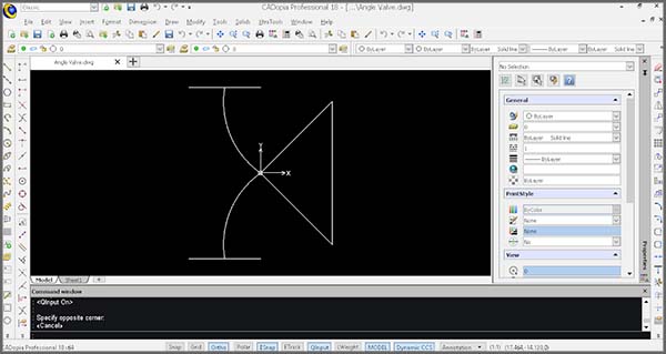
CADopia 18 adds new functionality and refinements to make it a perfect CAD software for drawing production. You can use CADopia for creating, editing and viewing technical drawings.
The new functionality introduced in CADopia 18 include DWG 2018 support, new switchable User Interface, multileader, block tools, dynamic coordinate systems, 2D Spiral and 3D Helix, formulas and export to Excel, and miscellaneous usability and performance refinements.
All licenses are perpetual, they don’t expire. You can upgrade your purchased software at your convenience based on your requirements.
DWG 2018 Support
CADopia 18 supports reading the new DWG 2018 format drawing files and it continues to maintain compatibility with legacy DWG files.
Read and modify DWG files up to the latest version of this popular format (R2018). With CADopia 18 you can create or modify drawings and save them directly in DWG, up to AutoCAD® version 2013-2018 or any previous version. Your files can easily be shared with users of other CAD software such as AutoCAD® or MicroStation®. Other file formats supported include DXF, DWF, DWT or DGN (import).

New User Interface
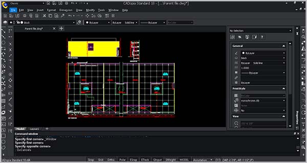
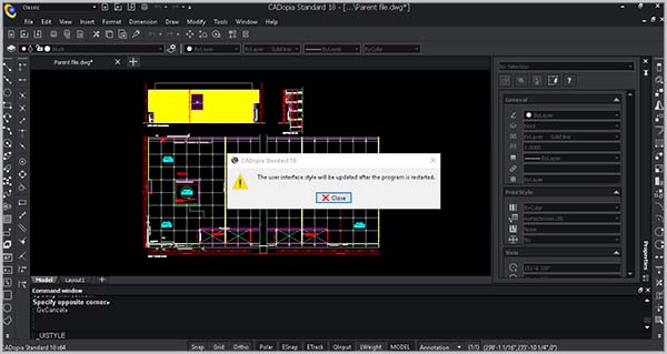
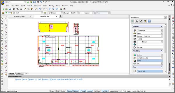
CADopia has a new dark user interface, but you have the option to switch between the dark user interface and the white user interface by picking Switch UI Style from the Windows menu or typing _UISTYLE on the command line. The UI Style change takes place when you restart the application. You can also switch between ribbon and classic interfaces.
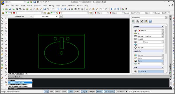
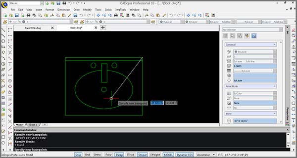
Redefine Base Point of a Block
Change the base point of a block in your drawing, without exploding it. The new REDEFINEBASEPOINT command allows you to set a new base point for blocks. The new base point applies to the selected block and any previous insertion of the block get the new base point. This eliminates the steps of exploding and recreating the block before replacing it.
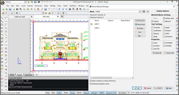
Edit Block Attributes properties
The new Block Attributes Manager lets you redefine the attributes definitions of a block intuitively. You may define the visibility of an attribute, change the order, default values and other parameters, directly from a comprehensive dialog box.
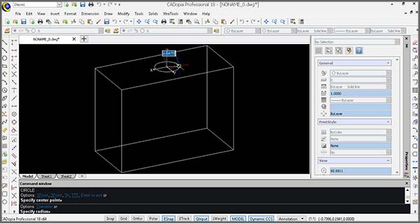
Modify 3D solid primitives
New grip points in 3D solid primitives allow you to edit the dimensions of the solid directly. You may also use Quick Input to input a new value. Alternatively, you may change the shape by editing the values in the properties palette for the selected primitive.

Dynamic Custom Coordinate System (CCS)
Enable the Dynamic CCS to automatically align the coordinate system to the face you are editing. The Dynamic CCS can be turned on or off from a toggle in the bottom of the User Interface or by pressing F6. When enabled the CCS gets aligned to the surface automatically as you move over it.
2D SPIRAL and 3D HELIX
Create 2D spirals and 3D helices. The HELIX is a new entity that can be used in 2D to create spirals or in 3D to create helices. You may further use an HELIX as an extrusion path and create complex shapes such as bolt threads, circular stairs or ramps.

Formulas in Tables and Export to Excel
Use formulas in tables from within your drawings and improve workflows with Microsoft Excel® using import from/export to Excel feature.
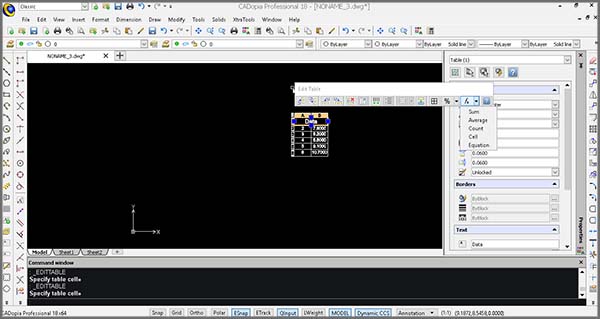
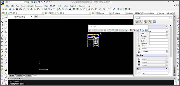
On selecting a table, you will now see a contextual ribbon that allows you to insert formulas such as the sum or average of a column or equations. You may also use Paste selected to copy a table from Excel or use the new EXPORTTABLE command to export a table in your drawing to a .CSV file that can be further processed in Excel or other spreadsheets.
Annotate with MultiLeaders
Use MultiLeaders to annotate drawings with a single text and multiple arrows.
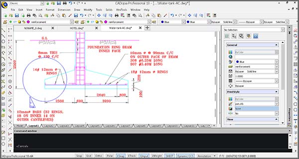
The command MULTILEADER is also associated with the MULTILEADERSTYLES command for creating and managing MultiLeader styles and for maintaining a consistent style across your drawings. EDITMULTLEADER is used to edit MULTILEADER entities. For example, you can add another arrow to the same text.
Usability Improvements
Move entities incrementally with arrow keys, copy entities to current layer or paste content from the clipboard to the current layer.
You may now select entities and move them with the arrows of your keyboard by an increment that can be adjusted in the options. This helps to adjust the position of entities in an interactive way.
While using the COPY command you may also select to copy entities directly to the current layer instead of their original layer. Similarly, the PASTE command allows you to place the content of the clipboard to the current layer.
